Day 04 — Bus topology & time sync: who owns the clock
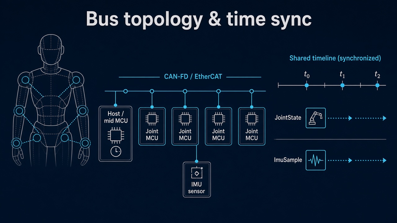
Day 02 froze JointState / JointCommand. Day 03 added ImuSample, ContactState, and EstimatorState. Those structs are theater if joints and the IMU are stamped on different clocks, or if “latest packet” quietly replaces sample time.
Today freezes the wire and the timeline: which bus topology you run, who owns the master clock, and how the physical plant and the digital twin share one timebase without silent lag.
The bus is a control surface
Bandwidth is the brochure number. What balance and contact actually need:
| Property | Why it matters |
|---|---|
| Cycle / jitter | Estimator and WBC assume a period; jitter becomes phase noise in fusion |
| Max age | Stale or is worse than a dropped frame you detect |
| Ordering | Joint vs IMU vs contact must be mergeable on one timeline |
| Fault visibility | Bus-off, missed sync, CRC — publish them, don’t swallow |
A 1 Mb/s bus with known 200 µs jitter and stamped samples beats a “fast” USB poll that delivers whatever arrived last with no age field.
Rule: higher layers consume sample time in a named clock domain, never “the freshest buffer.” If you cannot defend age and domain, you cannot defend multi-rate fusion.
Physical firmware and the twin publish the same message map. In sim you may inject ideal time — but then you must document the lie and add the measured delay budget before you claim transfer.
Topology: pick a spine, then hang limbs
Humanoids are graphs of nodes (joint MCUs, IMU bridges, FT front-ends, host / mid MCU). Three common spines:
| Spine | Strengths | Costs / traps |
|---|---|---|
| CAN / CAN-FD | Multi-drop, cheap, many joint nodes; FD helps payload | Arbitration jitter under load; need a clear ID / rate plan |
| EtherCAT | Cyclic determinism, distributed clocks (DC), high PDO rates | Topology/cabling discipline; tooling; DC setup is not optional |
| Hybrid | EtherCAT spine + CAN/SPI on a limb board; IMU local to a joint MCU | Two clock domains unless you bridge time carefully |
Physical ↔ digital pairing for topology
| Physical | Digital twin / backing |
|---|---|
| Node IDs / station aliases | Same IDs in message map and URDF-adjacent config |
| Bitrate / cycle time () | Twin step or bus model uses (or documents ideal) |
| Who bridges IMU/FT | Same attachment: “IMU via joint 2 node,” not a magic host topic |
| Redundancy / ring break | Fault flags the twin can inject for policy tests |
Exercise: draw your real wiring once. Count hops from IMU to estimator. If the path is “SPI → joint MCU → CAN → USB gadget → ROS → Python,” write the budgeted age for that path before you tune balance gains.
Time sync: sample ≠ transmit ≠ receive
Three times show up in every packet path:
- — when the ADC / encoder latch happened (what control wants)
- — when the node put the frame on the wire (optional)
- — when the host saw it (easy to log, dangerous to treat as truth)
If nodes free-run, differences include transport and clock drift. Estimators that subtract “IMU time” from “joint time” using receive stamps invent phase.
Who owns the clock
Pick one master clock domain and name it in frames (e.g. host_mono, ec_dc, mcu0_tim2).
| Mechanism | Idea | Use when |
|---|---|---|
| EtherCAT DC | Slaves align to a distributed clock; latch near SYNC | EtherCAT spine; you need sub-cycle alignment |
| Sync / heartbeat frame | Master broadcasts time or a pulse; slaves discipline local timers | CAN-FD with a clear master |
| Host-stamped + max age | No shared sync; host records and enforces age budgets | Early bring-up only — graduate out before multi-contact |
| Explicit offset table | Rare offline measure of fixed delays | Static pipelines you cannot retime |
Do not mix “IMU on USB wall time” with “joints on MCU tick” and call it fused. Convert into one domain or keep separate estimators until you can.
Shared wire header (extend Day 02 / 03 APIs)
Mirror the muscle and sensing APIs with an explicit header every cyclic sample carries:
BusHeader:
  node_id, seq
  t_sample          # in clock_domain
  t_tx?             # optional
  clock_domain      # e.g. "ec_dc" | "host_mono"
  age_budget_ms     # contract: drop/flag if exceeded
  faults            # sync_lost, bus_off, crc, seq_gap, ...

JointState  ⊇ BusHeader
ImuSample   ⊇ BusHeader
ContactState ⊇ BusHeader
Higher layers (WBC, RL, teleop) should not care whether the frame arrived on EtherCAT PDO or CAN-FD — only that t_sample and clock_domain are honest.
If the twin publishes perfect JointState at step and hardware delivers the same fields 3 ms late with jitter, policies trained in the twin will hate the real bus. Either model the age budget in sim or keep a bus replay layer that both sides can feed.
Rates that fit a humanoid spine
Illustrative starting points (measure yours; do not worship the table):
| Stream | Typical cyclic rate | Notes |
|---|---|---|
| FOC current (local) | 10–20 kHz | Stays on the joint MCU — not on the spine |
| JointState on spine | 1–5 kHz | Position/velocity/ for mid-tier |
| ImuSample | 200–1000 Hz | Often local SPI → joint node → spine |
| ContactState | 0.5–2 kHz | Impact path needs the high end |
| Estimator in | matches slowest honest input | Age flags beat interpolated fiction |
Spine cycle should be an integer multiple story: e.g. EtherCAT 1 kHz with local FOC at 20 kHz, or CAN-FD joint frames at 2 kHz with IMU every other cycle — written down, not accidental.
Bring-up sequence (before you trust fusion)
- Node map — every MCU and sensor bridge named; matches wiring and frames.
- Message map — IDs/PDOs for Day 02/03 structs; no anonymous “debug CAN.”
- Empty-bus jitter — master cycle alone; log period histogram.
- Loaded bus — all nodes at target rate; watch arbitration stalls / lost frames.
- Sync on — DC or heartbeat; measure skew between nodes (scope or hardware timestamp).
- Contracts —
t_sample,clock_domain,age_budget_ms, fault bits live in CI logs. - Then close estimator / balance loops that consume multiple sensors.
Skip to step 7 and you will debug “IMU lag” for a week when the real bug is an unsynced free-running node.
Failure gallery
| Symptom | Likely bus / time cause |
|---|---|
| Balance OK in twin, tips on hardware | Twin used ideal time; hardware age never modeled |
| CoP / IMU events always “late” in plots | Using as ; USB or non-RT bridge |
| Joints smooth, attitude chatters after motors spin | CAN load / priority; IMU frames starved under arbitration |
| Seq gaps only on one node | Bad termination, stub length, or that node’s TX queue |
| Works until EtherCAT cable nudge | Ring/line topology break; missing link-down fault handling |
| Estimator diverges after hours | Clock drift between domains; no sync discipline |
| “Latest” joint + old IMU looks fine until impact | Age budget not enforced; impact needs aligned stamps |
What to freeze this week
Extend frames (and your bus config repo) with:
- Spine choice: CAN-FD / EtherCAT / hybrid — and why
- Node ID map; which node bridges each IMU / FT
- Named
clock_domainand who is time master - Cycle time , per-stream rates, and
age_budget_msper message class BusHeaderfields your firmware and sim will carry- Fault bits that force a safe torque policy (bus-off ≠ “hold last forever”)
The lesson is not “buy EtherCAT because humanoids are fancy.” It is make the wire and the clock the same story in silicon and in the twin, so Day 03’s sensing APIs stay honest under load.
Next
Day 05 — Power domain and BMS: brownout under peak torque, DC bus sag on the same spine, and how voltage faults must cut torque before the estimator invents a new reality.