Day 02 — Joint-level embedded: FOC, encoders, current as muscle
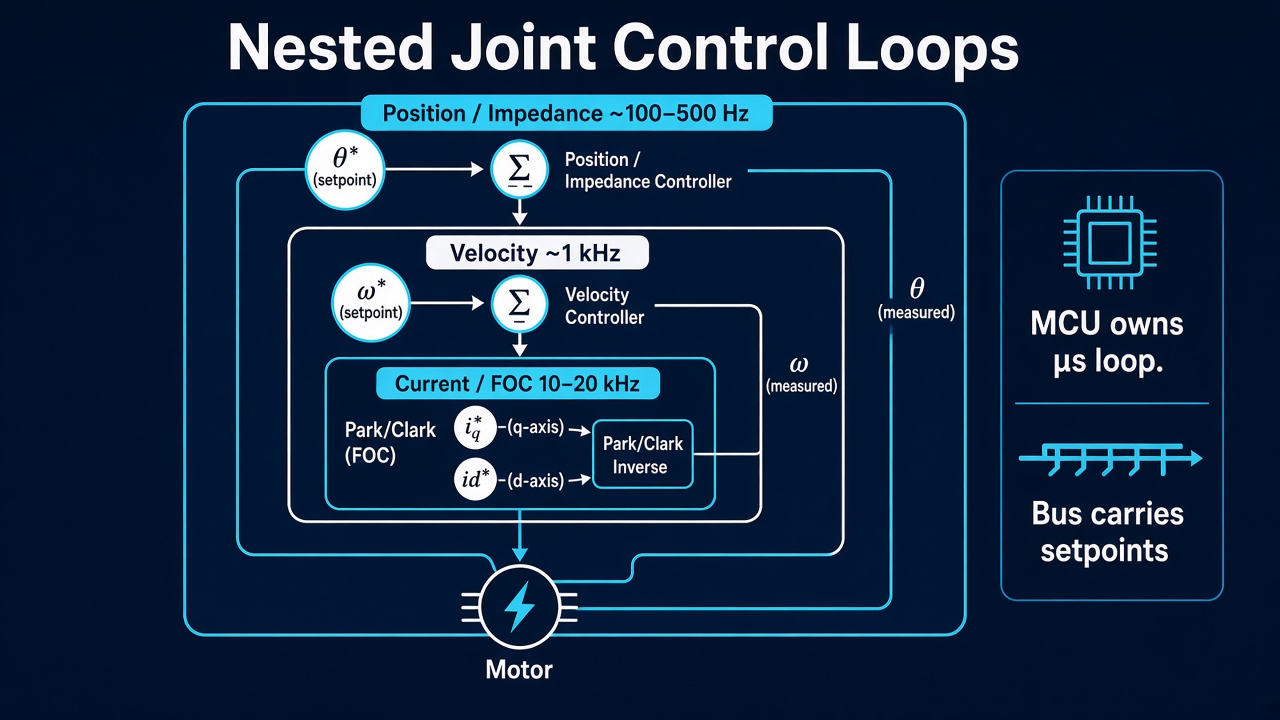
Day 01 left you with one rule: one joint, end-to-end, before you chain limbs. Today is what that joint is electrically and digitally. The muscle of a humanoid is not the motor casing. It is regulated stator current, transformed into torque through geometry you must know and measure.
If you skip this layer and jump to “impedance control” or “RL walking,” you are commanding a ghost. The physical plant only hears voltage and current.
Mental model: three nested loops
A modern joint drive is three feedback loops nested by speed. Outer loops are only as honest as the inner ones.
| Loop | What it regulates | Typical rate | Sensor |
|---|---|---|---|
| Current (FOC) | , in the rotor frame | 10–20 kHz | Phase current shunts / hall sensors |
| Velocity | (joint or motor) | 1–5 kHz | Encoder (differentiated or observer) |
| Position / impedance | , or vs error | 1–2 kHz | Encoder + (optional) torque sensor |
Rule: never close an outer loop until the inner one is flat, stable, and logged. A beautiful trajectory planner on a humming, unstable current loop is theater.
Physical build and digital twin share this same nesting. In firmware you tune PI gains on . In sim you need an equivalent: either a first-order current lag + torque constant, or a full electrical model. If sim torque appears instantly when you set a command, your digital twin is lying about bandwidth.
Why FOC (and what it actually does)
A brushless PMSM (permanent-magnet synchronous motor) does not have a single “torque wire.” Three phase voltages create a rotating magnetic field. Field-oriented control rotates your control frame with the rotor so that:
- (quadrature) produces torque (roughly for a surface PMSM — pole pairs, flux linkage)
- (direct) is held near zero for max torque-per-amp (or set negative for field weakening at high speed)
You measure two phase currents (the third is if the winding is balanced), transform them with a Park/Clarke transform using electrical angle, run PI on and , inverse-transform, and PWM the inverter.
Embedded consequences that bite humanoid builders:
- Electrical angle ≠ mechanical encoder angle. Multiply by pole pairs. Get this wrong and FOC becomes a heater that randomly produces torque.
- Current sense must be fast and calibrated. Offset error in a shunt amp becomes a DC torque bias. At a knee or ankle, that bias is a constant push into the ground or into the air.
- PWM frequency and dead-time matter. Dead-time distortion looks like torque ripple at low speed — exactly where a humanoid stands and shifts weight.
- The MCU owns this loop. Do not stream FOC over Wi-Fi. EtherCAT / CAN-FD can carry torque or current setpoints; the 20 kHz loop stays on the drive.
Physical ↔ digital pairing for FOC
| Physical | Digital twin / backing |
|---|---|
| Motor datasheet: , pole pairs, , resistance | Same constants in plant model; log identification runs |
| Shunt / hall current sense + ADC timing | Sample-and-hold delay in sim; noise model optional but offsets matter |
| Inverter DC bus voltage | Bus voltage as a state (brownouts change available voltage → current bandwidth) |
| FOC firmware (same gains you flash) | Mirror bandwidth: filtered by ~1/(2π·f_c) where f_c ≈ current-loop crossover |
Exercise: command a step in , log measured at ≥10 kHz. Fit rise time. Put that same rise time in sim. If walking later “works in MuJoCo but not on hardware,” check here first.
Encoders: you control what you measure
Joint control quality is dominated by angle sensing, not by how clever the outer controller is.
Common choices on humanoids
| Type | Where | Strengths | Failure modes |
|---|---|---|---|
| Magnetic absolute (on-axis / off-axis) | Joint output | Absolute on boot; compact | Soft-iron distortion; eccentricity → harmonic error |
| Optical incremental + index | Motor or joint | High resolution, low noise | Needs homing; dust/oil; cable flex |
| Dual encoder (motor + joint) | Both sides of gearbox | Estimates torque via twist; catches backlash | Two calibrations; more wiring |
| Resolver | Harsh environments | Robust | Analog front-end; lower resolution unless careful |
Output-side absolute is what whole-body control wants: joint angle in the URDF frame after power cycle. Motor-side incremental is what FOC commutation and high-bandwidth velocity want. Serious limbs often use both — motor encoder for FOC, joint absolute for kinematics and safety.
Encoder zero is a contract
Day 01’s frames already reserved a row for encoder zero. Fill it per joint:
- Mechanical stop? Mid-range? Calibrated fixture?
- Sign: does increasing encoder count match the right-hand rule on the named joint axis?
- Gear ratio and direction between motor encoder and joint angle
Firmware, CAD, and URDF must agree on that sentence. One flipped sign and your “impedance” joint injects energy.
Digital twin side
- Publish the same joint angle the controller uses (after gearing and zero), not a raw count.
- Model backlash and compliance if you have dual encoders — or at least a deadband — or sim will be stiffer than reality.
- Never differentiate raw counts without thinking: velocity estimates need filtering or an observer; naive at 1 kHz amplifies quantization into torque chatter.
Current as muscle
Torque is what moves the body. For a well-modeled PMSM, is your muscle activation. Thinking in voltage or in “duty cycle” is thinking in open-loop hope.
Practical chain on a geared joint:
where is gear ratio, efficiency (direction-dependent!), torque constant.
Why humanoids care more than robot arms:
- Gravity bias is always present. Standing is continuous torque, not a move-and-hold.
- Contact: when the foot hits, you want force, not a position bang into the floor. Force comes from current (or a torque sensor outer loop around current).
- Thermal: continuous heats windings. Muscle has a duty cycle. Log motor temperature or estimate ; thermal foldback is a first-class behavior, not an afterthought.
What to log on day-zero joint bring-up
Minimum viable instrumentation for one joint:
- , (command vs measured)
- Bus voltage
- Motor and/or joint angle
- Estimated from current × ×
- MCU loop timing (max / jitter of the FOC tick)
If you cannot plot those five, you do not yet have a joint — you have a motor that spins.
Physical ↔ digital: same “muscle API”
Define one interface both worlds obey:
JointCommand:  iq_ref | tau_ref | (later) impedance {K, D, theta_des}
JointState:    theta, omega, iq_meas, tau_est, fault_flags
Firmware implements it on CAN/EtherCAT. Sim implements it as a motor plugin. Higher layers (WBC, RL policy, teleop) should not know whether the plant is metal or MuJoCo.
Bring-up sequence (do this on the bench)
- Spin uncoupled. No link mass. Verify commutation: smooth torque, no cogging from bad angle. Check , tracks steps.
- Identify and direction. Hang a known lever + mass or use a torque sensor. Sign must match
frames.md. - Close velocity, then position with conservative gains. Measure tracking bandwidth.
- Add the link inertia (or a dummy mass). Retune. Note how gravity feedforward from the digital model helps — this is the first real payoff of the twin.
- Only then attach to a multi-joint chain.
Skip steps and you will debug “walking” while a single drive is thermally folding back or losing encoder sync.
Failure gallery (memorize these)
| Symptom | Likely layer |
|---|---|
| Motor hums, no smooth torque | Electrical angle / pole pairs / encoder alignment |
| Constant drift force at “zero torque” | Current sense offset or bias |
| Fine at no load, oscillates under gravity | Gains / bandwidth; missing gravity FF from model |
| Works until warm | Thermal derating, resistance rise, magnet temp |
| Sim tracks; hardware lags then overshoots | Current-loop lag not in twin; or gearbox backlash |
What to freeze this week
Update frames for your first joint:
- Motor type, pole pairs, gear ratio , assumed
- Encoder type(s), counts/rev, zero definition, sign
- Current loop rate and where it runs (which MCU)
- The
JointCommand/JointStatefields your bus will carry
Physical CAD and digital URDF both reference that row. The lesson is not “buy a better FOC chip.” It is make current, angle, and torque the same story in copper and in code.
Next
Day 03 — Sensing beyond the joint: IMU placement, contact/force, and why estimation rate is a first-class design choice.